

Buyer's Guide: Turbochargers
12 min read
RideBuilder
Turbocharger Buyer's Guide
Turbochargers harness the power of exhaust gases to compress incoming air, allowing your engine to generate significantly more power. Exhaust gases spin the turbine, which drives the compressor, forcing more air into the engine. Turbocharging your engine can seem overwhelming but this guide breaks down everything you need to know so you can hit your horsepower goals. This guide covers turbocharger fundamentals, key specs to understand when choosing a turbo, and the supporting modifications required to run one safely.
What is a Turbocharger?
Every turbocharger consists of three main pieces:
-
Turbine (hot side): The turbine wheel sits in the exhaust stream and is spun by hot exhaust gases leaving the engine.
-
Compressor (cold side): Connected to the turbine by a rotating shaft, the compressor wheel is driven by the turbine and pressurizes incoming air before it enters the engine.
-
Center housing: Contains the shaft connecting the turbine and compressor, along with the bearings that support it. The center housing also has oil inlet/outlets for proper lubrication and coolant inlet/outlets for proper cooling.

How Turbocharged Systems Work
A turbocharged system involves several interconnected components working together on both the intake and exhaust sides of the engine.

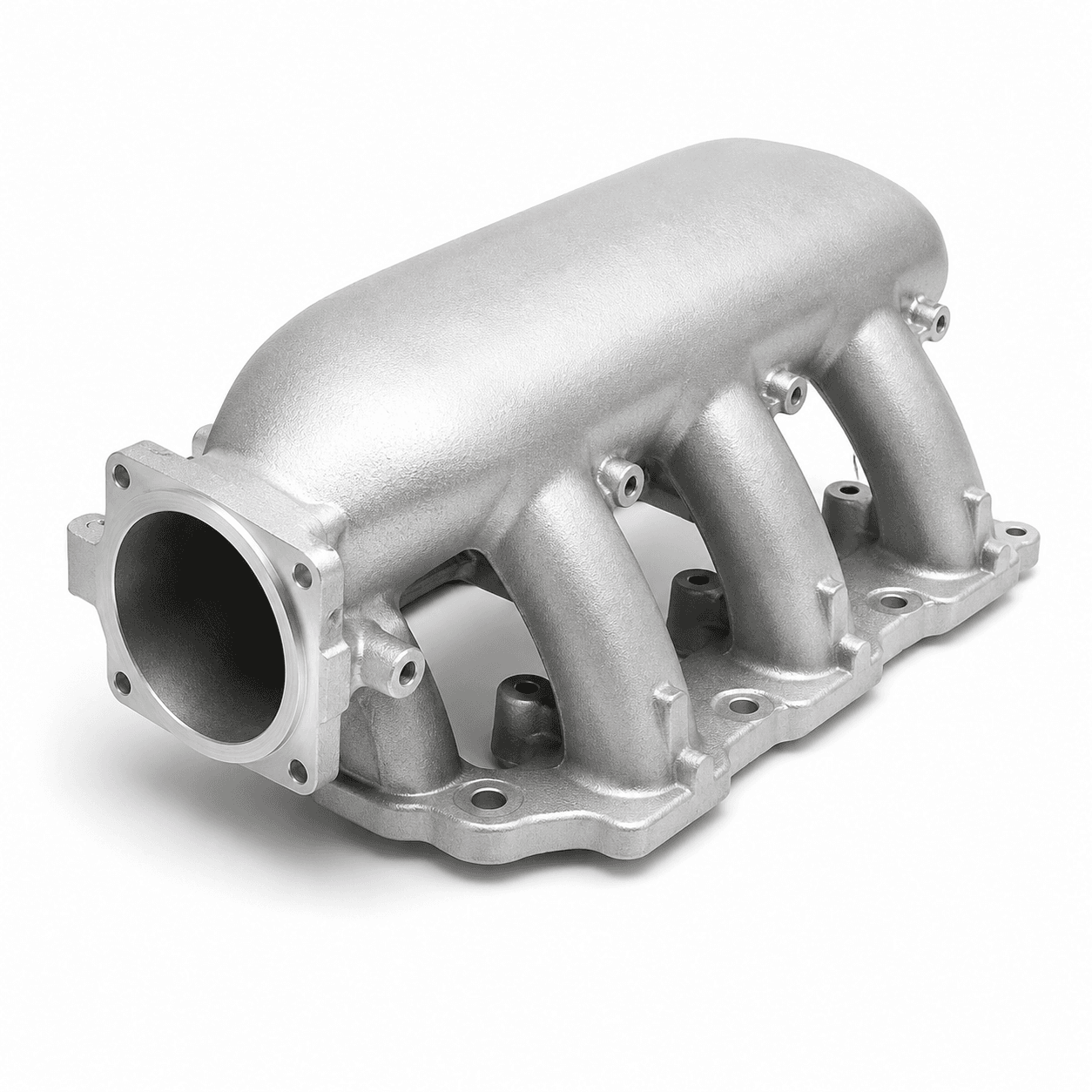
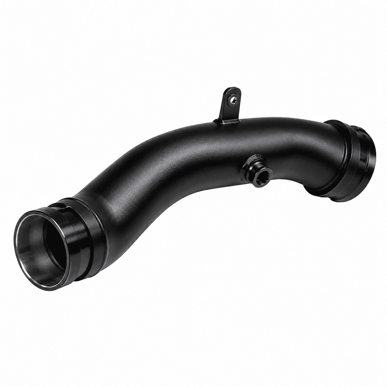
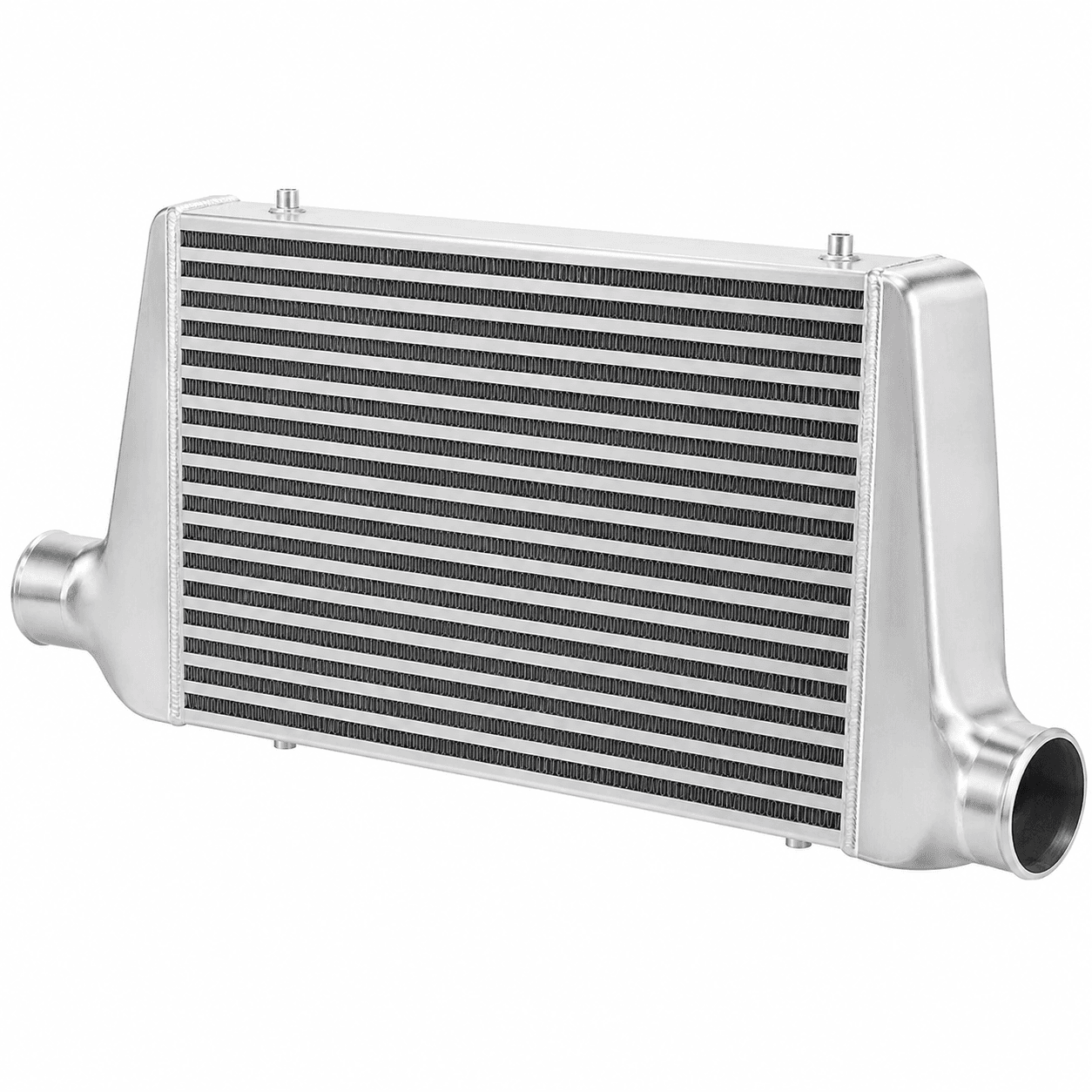
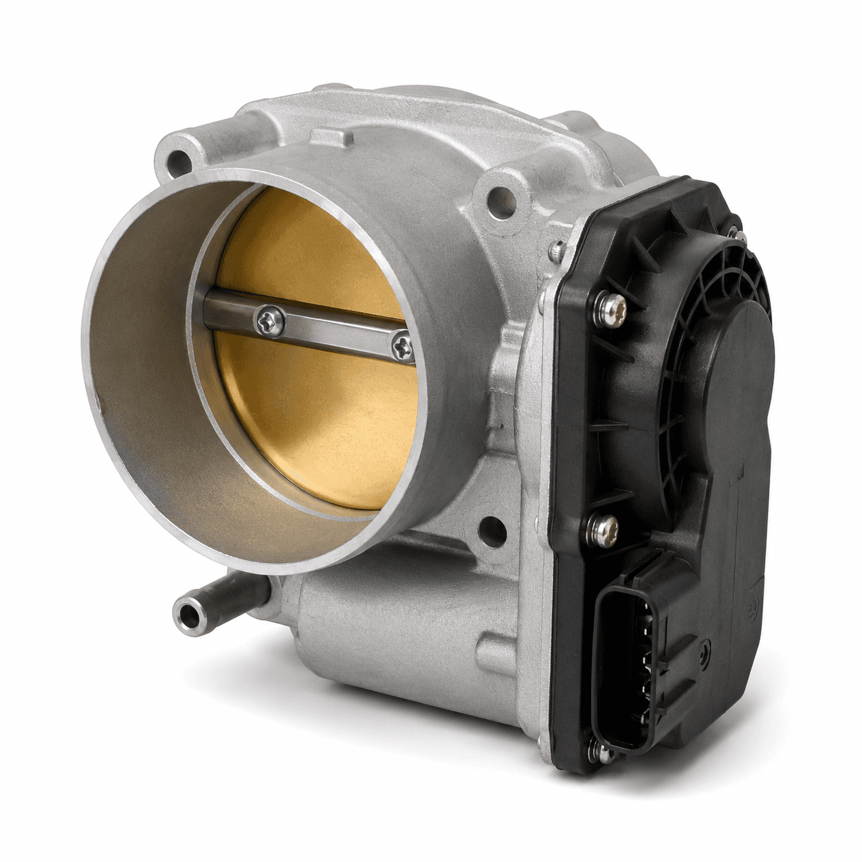
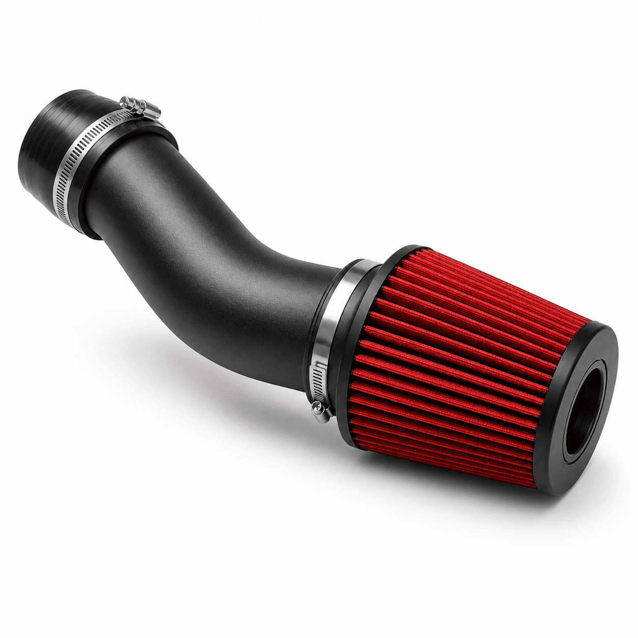
Intake side: Ambient air enters the compressor, where it is pressurized. Compression raises the air temperature, so the hot "charged air" must pass through an intercooler before entering the engine. Cooler air is denser and carries more oxygen per unit volume, increasing power output and reducing the risk of knock. The cooled air then flows through the throttle body and into the intake manifold where it enters the engine.
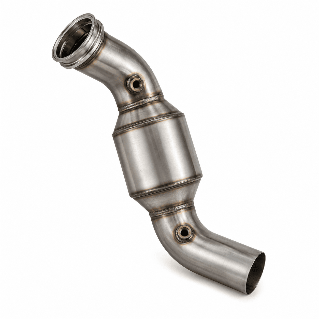
Exhaust side: Hot exhaust gases are routed to the turbocharger by the exhaust (turbo) manifold, where they spin the turbine wheel. Exhaust gases exit the turbocharger through a downpipe, which connects to the rest of the exhaust system.
Several components regulate and protect the system. Click on the names to learn more.
-
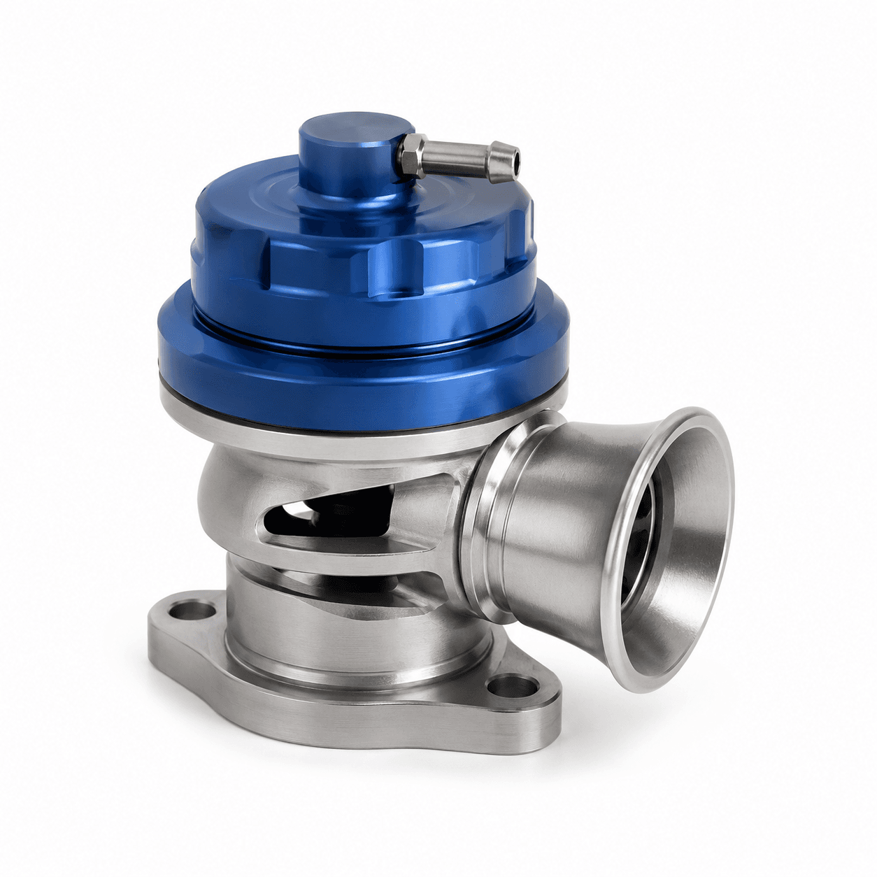
Blow Off Valve: Releases excess pressure from the intake system when the throttle closes, protecting the turbo from compressor surge.
-
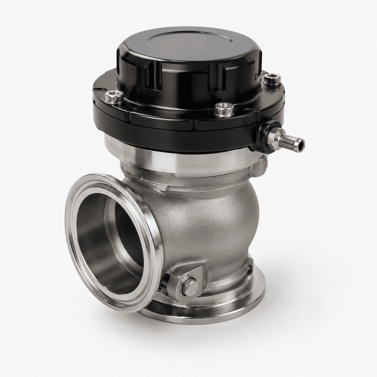
Wastegate: Bypasses exhaust gas away from the turbine to regulate maximum boost pressure.
-
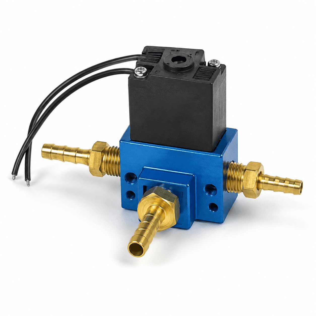
Boost Controller: Provides additional control over boost pressure.
-
Intake Air Temperature (IAT) Sensor: Provides data to the electronic control unit (ECU) about incoming air temperature, informing proper fuel delivery and spark timing. IATs must be placed after the intercooler.
-
MAP Sensor: Provides data to the ECU about air pressure within the intake manifold, helping the ECU calculate the optimal amount of fuel to inject. Some turbocharged systems use mass air flow (MAF) sensors instead of MAP sensors to meter air entering the engine.
Turbo Lag vs. Boost Threshold
These two terms are related but describe different things and are frequently confused.
Boost threshold is the engine RPM at which the turbo begins generating boost pressure. It is determined primarily by A/R ratio, aka the turbo's size. A large turbo might generate boost starting at 4,000 RPM, while a small turbo might generate boost at only 2,000 RPM. Boost threshold affects driveability. A higher boost threshold means less available power in lower RPM ranges.
Turbo lag is the delay between pressing the accelerator and feeling the turbo's power kick in, even when operating above the boost threshold. It is caused by the time needed to spool the turbine and compressor wheels fast enough to generate meaningful boost pressure. Some lag is unavoidable, but it can be minimized with smaller turbos, twin-turbo setups, or anti-lag systems.
In summary, boost threshold is the RPM required to generate boost pressure while turbo lag is the delay between pedal press and power delivery. For street builds, reducing boost threshold and turbo lag are usually the priority. For track or drag builds, peak power may matter more.
A/R Ratio
The A/R (Area/Radius) ratio is one of the most important specs on a turbocharger because it describes how "large" it is. It's calculated by dividing the cross-sectional area of the turbine inlet by the radius from the center of the turbo to the center of the inlet. While both the turbine and compressor housings have their associated A/R ratio, the turbine's A/R ratio affects performance most and is what people refer to when they discuss A/R ratios.
Smaller A/R turbos spool faster due to increased exhaust gas velocity, reducing both boost threshold and turbo lag. Small A/R turbos provide great low end performance but reduce maximum airflow, choking the engine at high RPM and limiting peak power. Smaller A/R turbos (eg. less than 0.80) are great for street cars, rally/autocross, and smaller displacement engines.
Larger A/R turbos reduce this airflow restriction, allowing for higher peak power and excellent high RPM performance. Larger A/R ratios suffer from high boost thresholds and slower spools up due to the slower exhaust gases, making them less desirable for street applications. Large A/R turbos (eg. greater than 0.80) are great options for track cars, drag racing, large displacement engines, and towing applications where most time is spent at the upper end of the RPM range.
Oversizing your A/R ratio for your engine and application is one of the most common mistakes in turbo builds. A large turbo on a small street car produces dramatic lag that makes it unpleasant to drive, even if peak power numbers look impressive on paper. Ultimately, the A/R ratio of your turbo determines whether it operates best in low RPM ranges, mid RPM ranges, or high RPM ranges.
Turbo Compressor Maps
A turbo's compressor map is the most powerful tool for properly sizing a turbocharger. It plots pressure ratio on the y-axis against mass flow rate on the x-axis, showing exactly how a turbocharger performs across its operating range and how efficiently it does so.
Mass Flow Rate
Mass flow rate is measured in lbs/min and describes the volume of air entering the engine. To convert from lbs/min to maximum horsepower, the rule of thumb is to multiply by 10. For example, a turbocharger operating with 30 lbs/min of airflow would be capable of generating approximately 300 horsepower. For most enthusiasts, this approximation is appropriate.
Pressure Ratio
Pressure ratio describes the ratio of pressure coming out of your compressor compared to pressure going in. The formula is:
Pressure Ratio = (Boost Pressure + Atmospheric Pressure) / (Atmospheric Pressure - 1)
Atmospheric pressure at sea level is 14.7 psi, although this may vary slightly depending on your altitude. The 1 psi subtracted from the denominator accounts for assumed pressure losses from the air filter and intake piping.
For a turbocharger running 10 psi of boost:
Pressure Ratio = (10 psi + 14.7 psi) / (14.7 psi - 1 psi) = 1.8
Efficiency Islands
With your target mass flow rate (based on horsepower goals) and pressure ratio (based on target boost pressure), you have the coordinates to plot your operating point on the compressor map. The concentric rings on the map are called efficiency islands, labeled with percentages representing compression efficiency. Your goal is to have your operating point fall within the peak efficiency island. A point that falls far outside the islands suggests the turbo is not well-matched to your application.
Choke Line, Surge Line, and Speed Lines
-
Choke line: Sits on the right side of the efficiency islands, representing the maximum airflow a compressor can handle before efficiency plunges.
-
Surge line: Sits on the left side of the efficiency islands, representing when the turbocharger is not receiving enough air flow to support the boost pressure it generates.
-
Speed lines: Horizontal arced lines indicating turbocharger wheel RPM at various points.
Additional Turbo Specifications
Trim
Trim describes the ratio of the compressor wheel's inducer (inlet) diameter to its exducer (outlet) diameter, squared:
Trim = (Inducer Diameter / Exducer Diameter)^2 * 100.
While trim values exist for both the turbine and compressor wheel, compressor wheel trim affects performance most. Trim values for compressor wheels commonly fall between 45-65. High trim values mean more peak airflow, but slower spool up.
Bearing Type
Bearings support the shaft between the turbine and compressor wheels.
-
Journal bearing: Longer lifespan, lower cost, slightly slower spool.
-
Ball bearing: Faster spool, reduced turbo lag, higher cost. Generally the superior choice for performance applications.
Turbine Scroll Type
-
Single scroll is the standard option. These turbos are simpler and less expensive, but can suffer from exhaust pulse interference between cylinders, slightly reducing efficiency.
-
Twin scroll turbos separate exhaust gases into two separate streams, reducing interference, improving efficiency, and reducing turbo lag. Twin scroll turbos require specially designed exhaust manifolds and two separate wastegates.
Inlet/Outlet Flanges
Connection types and sizes must be confirmed on all four connection points before purchasing:
-
Turbine Inlet: Match your exhaust manifold flange to your turbine inlet flange. Common flanges are T3, T4, T6, and V-band.
-
Turbine Outlet: Match your downpipe flange to your turbine outlet flange. Common flanges are V-band or 3-bolt.
-
Compressor Inlet: Match intake piping diameter to your compressor inlet diameter. Connected using silicone couplers and clamps.
-
Compressor Outlet: Match intercooler piping diameter to your compressor outlet. Connected using silicone couplers and clamps.
Supporting Modifications
To safely turbocharge your system, go through the checklist of supporting modifications below.
-
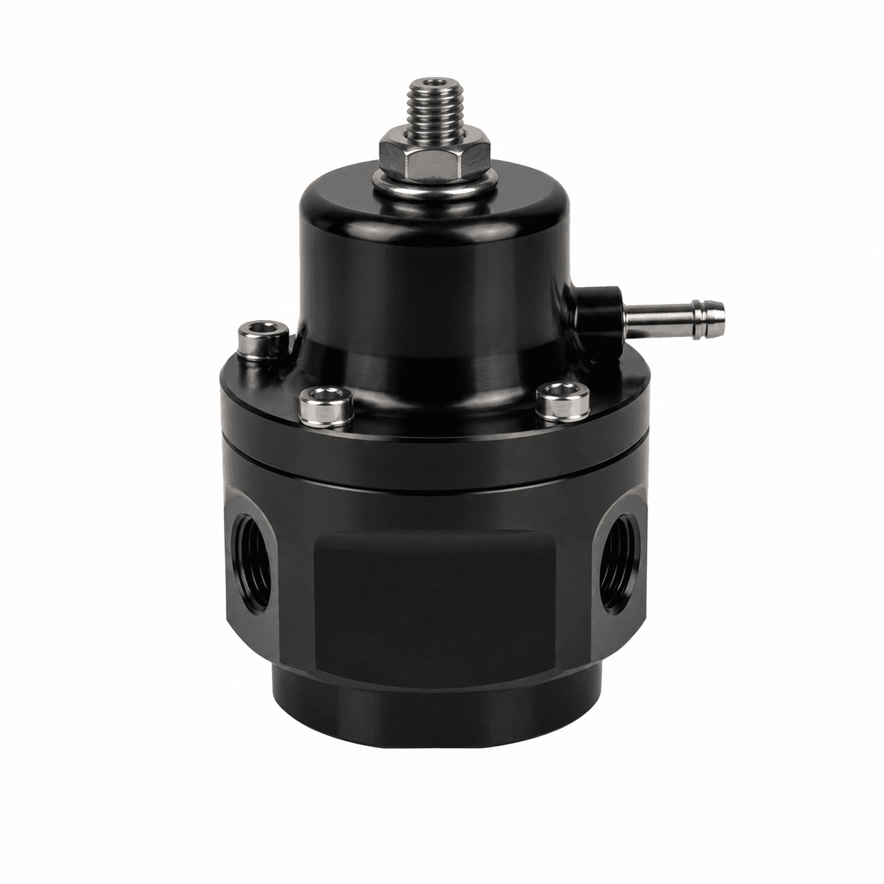
Fuel System Upgrade — Required: More air requires more fuel. Your stock injectors, fuel pump, and fuel pressure regulator should be replaced to support the additional demand. Read our fuel injector, fuel pump, and fuel pressure regulator guides for more information.
-
ECU Tune — Required: A proper tune is essential for safe and efficient operation with your new parts. Without it, the ECU cannot correctly manage fuel delivery or ignition timing under boost.
-
Intercooler — Strongly Recommended: Cools compressed air before it enters the engine, improving power and reducing risk of knock. Intercoolers are especially important for high boost applications or hot climates. Read our intercooler guide.
-
Blow-off Valve — Strongly Recommended: Prevents compressor surge and protects your turbocharger from damage. Any well-built turbo system includes one. Read our blow-off valve guide.
-
Wastegate: Regulates maximum boost pressure. Internal wastegates are prone to boost creep especially with large engines and high boost, which may require an upgrade to an external wastegate. Read our wastegate guide.
-
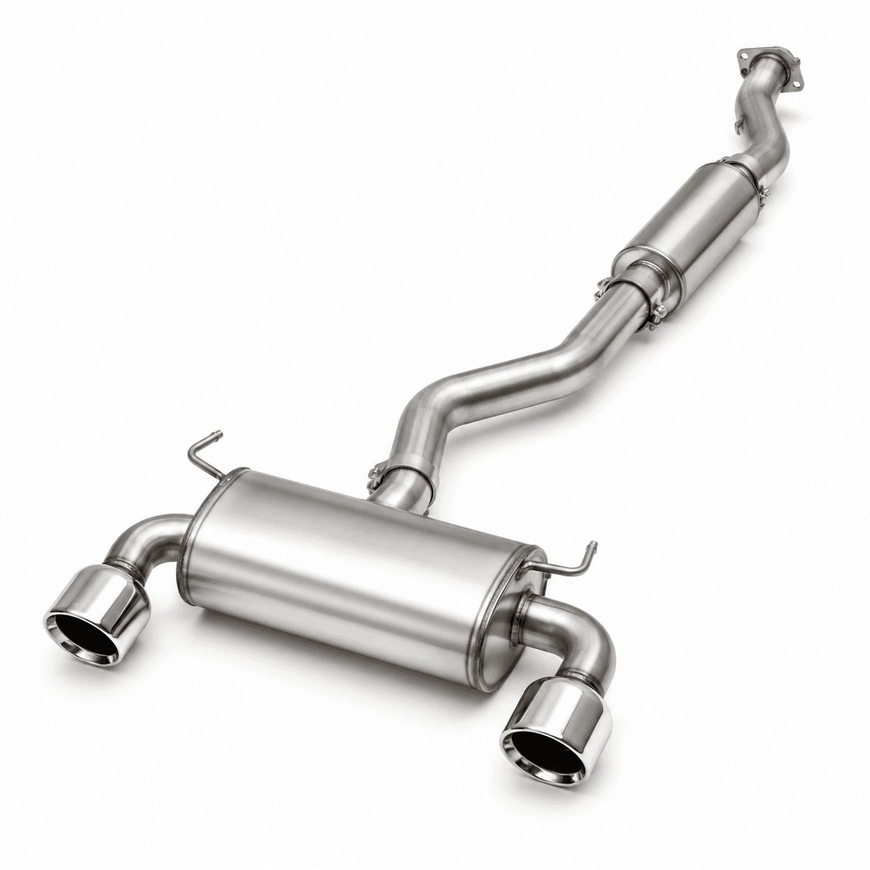
Exhaust System: Turbocharged systems are particularly sensitive to backpressure. Upgrading to a performance exhaust system is particularly powerful on a turbocharged build compared to a naturally aspirated one. Read our exhaust system guide.
Conclusion
A turbocharger is one of the most impactful modifications you can make to an engine, but also one of the most involved. Getting the most out of your build starts with choosing the right turbo for your application. Match your A/R ratio to your RPM range, use the compressor map to confirm your horsepower and boost targets fall within the efficiency islands, and verify flange compatibility across all four connection points. From there, make sure to pair your turbo with supporting modifications including an upgraded fuel system, intercooler, tune, and blow off valve at the minimum. You can find all the parts you need and plan your build on RideBuilder.